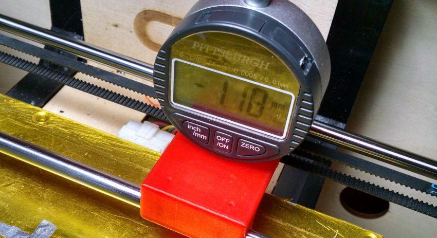
3D printers require a level build plate. We’re taking a look at how you can level your Replicator, CTC, Flashforge, or other Makerbot Replicator style printer build plate
Bill of Materials for this Build:
- Finger Guage (or sheet of paper)
- (Digital) Dial Gauge
- 3D Printed Jig
- Small Magnets (optional)
- Hot Glue (to adhere magnets)
Some newer extruders such as the Kossel style Deltamaker cleverly level the head instead of the plate, which proves a bit simpler. They’ve got there own weaknesses, of course, but a level plate generally isn’t one. For the rest of us we have to put up with leveling springs in three or four locations needing to be tightened to spec periodically.
As with any procedure you can severely damage yourself or your equipment. By reading this article you acknowledge that the author, this publication, and any other entity have no responsibility for damage or injury. Take all necessary safety precautions and make sure that any procedure will not cause damage or injury before going through with it.
So what’s an easy way to level the build plate? You can fiddle around with a finger gauge and manually level it repeatedly to .102mm or .004 inches (about the thickness of a sheet of paper) on all the points hoping that it’s dragging just right every time and you’re not getting a variance.
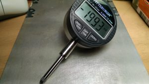
Or you can pony up 15$(USD) or so and get a digital depth gauge (ours was from Harbor Freight, pictured right). There are also tire tread depth gauges with the proper resolution for the job available in the 5$ range. We went with the classier dial style digital gauge jig as seen in the pictures. Link to the required jig on Thingiverse: (STL Files at Thingiverse)
You may want magnets as well. Gluing them in place on the print-out provides a bit more staying power to your jig. Less moving about while you’re setting the screws on your plate is definitely a plus but the design will clip on if you have trouble finding magnets.
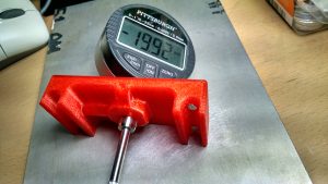
Digital depth guage installed in 3D printed jig with magnets
In addition to magnets re-sizing the inner diameter of the print out’s pass-through hole to the gauge might be necessary if there’s a variation to it on your meter. A bit of tape or smudge of dried adhesive on the inside of the opening can achieve the same goal if you’re not keen to pre-measure everything and alter the 3D drawings.
How does it all work? You’re still going to need your finger gauge (or paper) to level a single corner properly. Being careful not to hit the bed with your print head position the print head properly near one of the leveling screws and get it to the correct distance from the print bed. We accomplished this by moving the print head out of the way, manually moving the Z axis all the way to the top, then moving the print head near the screw with the built in jog function.
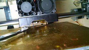
A finger guage balances under the print head to check the depth of clearance
While the build plate is positioned correctly next to the screw go ahead and level the build plate. On most printers this is accomplished by tightening or loosening the screw until your finger gauge (or paper) drags appropriately. Your 3D printer may differ.
Once that screw is tightened to the proper tension go ahead and move your print head(s) off to the side using the jog feature of the printer. With the printhead moved to the side place your jig on the printers carriage rods as pictured.
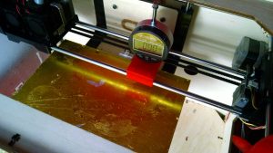
Zero the digital depth gauge by pressing “Zero” (or your equivalent) once it is mounted securely in place. With the gauge reading zero move your Y and Z axis around until the meter is roughly next to each one of the tensioning screws. Then add or remove tension with the screw until the gauge reads zero for each of the positions.
You’ll want to repeat your check until all four points read near zero. It generally takes a few passes.
That should be it! If that all worked for your 3D printer you should now have a leveled build plate.

