Blog

  • Fixing the PinePhone USB-C Dock and USB (network) Tether

    Fixing the PinePhone USB-C Dock and USB (network) Tether

    I’ve finally decided to pull my PinePhone Braveheart edition out of it’s box and plug it in. There’s a task for it; acting as an LTE hotspot through a USB tether for the network. That’ll plug into a tiny Atom based SFF computer running OpenWRT… but that’s a write-up for another day. On with fixing the PinePhone!

    Which phones this will effect is entirely unclear. If you’ve got Mobian, Manjaro, or some other mobile Linux OS loaded up on your PinePhone, and USB-C devices aren’t working, then the ANX7688 firmware might be the culprit.

    And cleaning loading the firmware in was the last thing I did in a series of changes. So some of those may be necessary as well. I’ll load up a default Mobian Bookworm (Debian) image and check when I’ve got this one backed up.

    Which was another issue. The Mobian installer images weren’t working, for some reason, and I had to revert back to a earlier non-installer image (the first of 2022) then apt upgrade it. That did bring it up to the current release and worked.

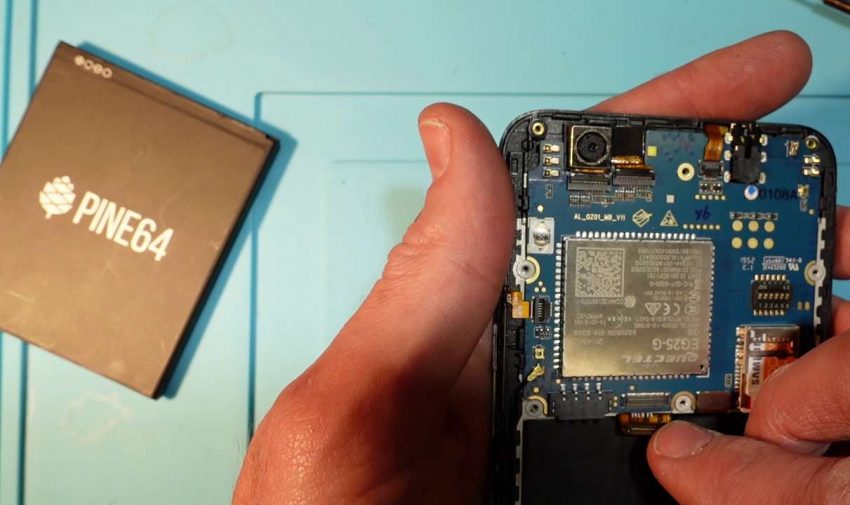
    To fix the USB Dock/USB Tether issue I needed to use the ANX7688  firmware found here. Installing it entails copy the firmware to /lib/firmware on the phone and triggering the flash with

    echo 1 > /sys/class/typec/port0/device/flash_eeprom

    I would only do that while it’s plugged in to mains and running stably. It may be possible to brick the phone if you, or the phone, does something unexpected. For more information refer to the code’s author at their website.

    What you’re doing there, in case you’re curious, is updating the firmware of the ANX7688. The ANX7688 is a mobile HD chipset that also handles quite a few other things; you can find out more at Analogix’s website.

    I’ll have more to write about fixing the PinePhone coming up. You’ll be able to follow along as I clean this platform up a bit and likely make a hash of it along the way!

  • Wii U Screen Replacement on a Gamepad

    Wii U Screen Replacement on a Gamepad

    Replacing a Wii U Screen on a Gamepad doesn’t have to be hard. While I was looking at the design I noticed that the digitizer attaches to a bezel instead of the LCD.

    Since the digitizer is attached to a removable bezel I took a look at how it attaches. As it turns out, it attaches with two pressure clips on each side!

    So instead of removing the adhesive on the digitizer from the Wii U screen you can remove the whole bezel. With digitizers being glass removing the adhesive often leads to a broken mess of sticky glass shards. Which isn’t a fun time to cleaning up.

    One thing that did trip me up a bit while taking the bezel off was a slight difference in design. While the replacement screen was clipped on the sides, top, and bottom the OEM was only clipped to the sides. And the (OEM and replacement) press fit seemed to have a different amount of pressure required to make them release.

    I didn’t bother to video opening up the Wii U gamepad. You can take the Y screws off on the back, carefully pull the internal cables loose, and unscrew the mainboard with little difficulty. If you’d like me to shoot a video teardown of the Wii U gamepad leave a comment; there are a still a few to rebuild.

    In the meantime, here’s a helpful iFixit repair guide with the screw locations. And check out my other game console repairs and teardowns while you’re here!

  • Qi Receiver Circuit Component Monday

    Qi Receiver Circuit Component Monday

    Qi (pronounced “chee”) charging is a wireless standard using inductor coils to punt power over a limited distance. We’re taking a look at the Qi Receiver part of the system. Generally used in cell phones I’m examining them this Component Monday for a (very low power) battery charge circuit.

    I purchased in two different parts from an Asian distributor. First we have a Samsung replacement part for a just-going-out model Galaxy phone. Second there’s a all-in-one processing board that outputs 5v and a bare copper coil.

    Neither of these parts were well defined in their sale listings. And that leads us to a problem. I’ll have to figure out from the circuitry and through practical testing how they work!

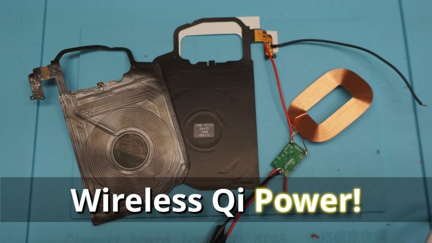
    Our Samsung part appears to be a bare coil. Peeling off a plastic/metal surface reveals a flexible PCB with a traced receiver coil. And I don’t see any electronics on the assembly.

    Which means our first part, the Samsung, is simply an induction coil without any additional circuitry. My hopes of getting high-end power regulators on the cheap from suruplus EOL Samsung replacement parts have been dashed.

    But those still aren’t a total waste. Because the Samsung Galaxy replacement coils are far more refined than the bare copper wire Qi receiver coil they should still make a good addition to the assembly.

    Once I cracked open the generic Qi receiver it seems to do the job it’s advertised to. When you supply a Qi charger to the coil it puts out a reasonable 5v.

    Qi Generic Receiver Circuit Board JX9086
    Close-Up Power Circuit from Generic Qi Receiver

    Lingering Qi-uestions on the Receiver

    Although a few lingering questions remain. First I’d like to know if that circuit will overheat if the range is long and the connection is tenuous. Second it’d be good to understand better what that circuit is doing. Third I’ll have to pull it up and see if those transitory spikes were just ghosts or if it’s very briefly blipping a high voltage down the line.

    From the number of ICs contained on it there seems to be quite a bit going on. And it is very compact for the amount of chips it contains.

  • PartKeepr VM on Debian 9 “Stretch” for VirtualBox

    PartKeepr VM on Debian 9 “Stretch” for VirtualBox

    PartKeepr, in case you haven’t used it, is a web-based inventory tracker. If you’ve got a small parts bin that needs looking after or a warehouse of assorted parts this PartKeepr VM is worth a look. This is similar to my ZoneMinder VM that’s due for an update.

    There are a dedicated group of volunteers maintaining the software as open source. They do a great job but as with any part-time project they’re limited in the hours they can afford to put into working on it.

    We were running into some problems implementing the latest GIT pull of PartKeepr on a current operating system release. Specifically, PartKeepr’s Symfony 2.x component. When I attempted to install PartKeepr 1.4 on PHP 7.1 or PHP 7.2 it fails. And this bug report will give you some insight why.

    What I found is that the latest versions of PHP , 7.1, 7.2, or 7.3 aren’t compatible with PartKeepr’s libraries. The dev team appears to be working on it, but until then a workaround is necessary.

    Which is why I created a VM based on Debian 9 “Stretch” that clears up any of the issues I found on install.

    PartKeepr VM Usage Notes

    My virtual machine build uses a stock Debian 8 “Jessie” installation built for PartKeepr updated to version 9. I then layered on the Git release of PartKeepr as per their instructions. If you need to update the git installation change to /var/www/html and type git pull

    I’ve created a /home/partkeepr/notes.txt file. It contains default passwords for the installation on the VM. You can change these using the PartKeepr Debian 9 “Stretch” setup notes for reference as needed.

    Your default username and password are partkeepr and partkeepr and SSH is enabled. You should change the password immediately.

    I hope this VM saves you some time and frustration. Because it was a bit of a pain to initially install. And I believe I’ve worked out the dependencies and setup correctly.

    If you have any interest in a download converted to work in KVM please let me know. I’ll see what I can do if it’s something folks are interested in.

    As usual, if you have a comment please leave it down below. I’m not constantly on the site but I do update it ever week or so to confirm comments and reply.

    Debian 9 “Stretch” PartKeepr VM – Created with VirtualBox 6.16

    11/05/2021 Update: In the virtual machine above you’ll want to add in the following line to the root user’s crontab (type “crontab -e” as root). It will get rid of the annoying “The following cronjobs aren’t running: partkeepr:cron:synctips” error relating to synctips on partkeepr startup.

    0 0,6,12,18 * * * /usr/bin/php /var/www/html/app/console partkeepr:cron:synctips

  • Does PTFE Tubing Cause PLA Filament to Snap? How About Moisture? And What is Mechanical Stress?

    Does PTFE Tubing Cause PLA Filament to Snap? How About Moisture? And What is Mechanical Stress?

    We’re going to perform an experiment to see if PLA filament will break from sitting in PTFE tubing. And will moisture cause it to snap even in a dry environment? Plus explain what “mechanical stress” means in this context.

    Back when I recorded the “Why Does My Filament Keep Breaking?” (https://youtu.be/SvpSxHLotMI) video I made the statement that mechanical stress was causing the filament to break over time. The filament in question sits in a dry box in a humidity controlled room.

    Both on the printer and in the box I noticed that the filament would snap when held straight. Which is an unnatural condition for the thermally formed PLA and what “mechanically stressed” refers to (in this case).

    There were numerous responses questioning PTFE tubing playing a roll in the filament breaking as well as some form of moisture ingress into the filament.

    Moisture can cause problems with PLA, to be sure. But not this particular problem in a dry environment.

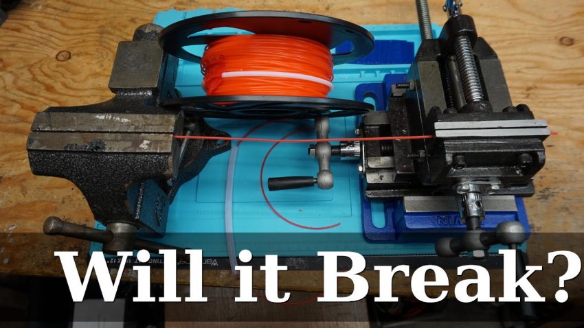
    I don’t believe either of those to play a significant roll in this case so we’re going to perform a quick experiment to A) explain what mechanical stress is (for this case) and B) show it breaking filament that is perfectly fine after the same amount of time on the roll sitting next to it on the bench. Inside and outside of PTFE.

    If you’d like to play along at home you can use a couple of books to hold the filament perfectly straight (not looped) between them.

    Let’s see what happens after a couple of days of artificially mechanically stressing PLA filament to see if it will break!

  • The McSega: Teardown of McDonalds Sega Handheld Game

    The McSega: Teardown of McDonalds Sega Handheld Game

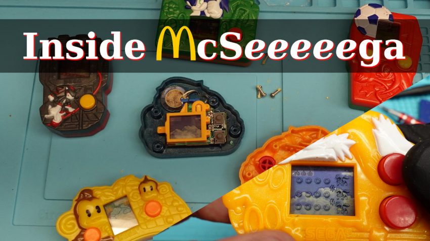
    McDonalds and Sega teamed up in 2004 to produce a series of handheld LCD video game. Since they were weirdly past their prime we’re taking a trip down memory lane and tearing one apart. And repairing it!

    Back in the 80’s portable gaming started innovating with LCD screens. Previously LEDs had ruled the handhelds with blocky single LED quarterbacks running for the touchdown or home plate.

    From my memory, with rare exception these were one or two player sports games. While the occasional space shooter got lumped in on the platform it was mostly football (of either variety), baseball, or basketball. And that was down to those games having mostly universal rules.

    The big sea change in handhelds came in the late 80s to early 90s with relatively cheap LCD based games. Suddenly you no longer needed to know what the dot represented; there was a picture of the Double Dragons, Contra, or Ninja Gaiden right there on the screen.

    And then the world moved on. Small displays became ubiquitous and cheap over time, processing got incredibly tiny, and second hand consoles flooded in. Our incentive to purchase a very limited single use handheld game evaporated over time.

    Repairing the McDonalds Sega Handhelds

    Which is why these handhelds from McDonalds struck me as odd when I brought them back to my workbench. Starting in 2004, Sega and McDonalds have sold (given away? prized?) old-school handheld consoles with their children’s meals. Presumably, for Sega, as some form of advertising.

    At first glance I’m struck by the triangle drive screws holding these together. I’m not a huge fan of security fasteners. Not only are they intending you to throw out the device but the manufacturer is going out of their way to ensure you do.

    After taking off the fasteners each game shows a remarkably varied interior design. Normally when you create a commercial mas-produced low price product you vary it as little over iterations as possible. Less variation, higher profit margins.

    Which isn’t what we’ve got here. With each individual unit I take apart I’m seeing a different internal assembly, molding, and overall design. Even the battery holders aren’t consistent between units (I’ll get the comprehensive picture gallery up below later today).

    But fortunately for me, the only real problem here is the battery. Even after 17 years there’s only a little corrosion on the battery terminals and they clean up nicely with baking soda.

    Of the problems I’m finding the more irritating is the adhesive on the back of some units. It looks like they may have been attached to a backer board on display.

    My personal complaints aside on fastener choice these do have some neat design decisions. I’m finding strangely durable construction here for a throw-away. Heavy protective plastic covers protect the LCD and the buttons are on par with most portable consoles.

    Power’s being provided by LR41 batteries (should you want to repair your own). Even though I have no idea what’s under those blob on chips it’s going to be energy efficient with a hard on/off switch. If you remember to turn it off!

    So that’s about all there is to these. Additional components are a zebra stripe rubber connector for the screen mated to the single layer PCB and roughly five capacitors and resistors. And a piezo element molded into the case for the bleeps and boops.

    I’ll have a photo gallery of the different models on my bench together later today. In the meantime, why not check out our other teardowns?

  • 3D Printer Repair – Replacing and Rewiring a Power Supply

    3D Printer Repair – Replacing and Rewiring a Power Supply

    Clean power for your 3D printer is a must-have item if you don’t want mystery problems cropping up. In todays segment on 3D printer repair I’m re-wiring this one of my printers and replacing the sketchy no-name power supply with a (better) quality Mean Well unit.

    There’s no part of a 3D printer that touches everything it does like the power supply. Each other powered component’s driven off it. So if your PSU is suspect or poorly wired you’ll quickly run into problems.

    I’m replacing a 12 volt power supply with a similar Mean Well (eventually, it’s initially a place-holder unit) part. If you’d like a more exhaustive list of power supply options the folks at RepRap.org have you covered.

    Our rebuild-in-progress Tronxy has a poorly wired, suspiciously unbranded power supply. There are artifacts showing up on some of the prints and the motors appear to be cutting out occasionally. Both of which point to the power supply.

    And if that wasn’t enough it sounds like a hovercraft a few seconds after powering up. My guess is that the bearings or bushings in the fan motor on the power supply have already started to fail after a few hours of use. Which is generally a sign of failures to come.

    Also adding to the trouble some of the wires in the screw down terminals were sitting in the their openings without having been screwed down. Others were soldered on the end. Which makes it tough to achieve an initial lock on the wire and will cause issues as the setup ages.

    So I’ve taken a look at each of the issues involved and cleaned them up. With the 3D printer’s power supply replaced it appears to be printing cleanly with no missed layers or skipping.

    Due to a heat issue after replacing the power supply I ended up cutting a 120mm fan in the cases bottom. While I’m fairly sure it wasn’t the power supply overheating, but the board, providing more cooling all-around solved the problem.

  • DIY Sanding Pad – Any Grit You Want

    DIY Sanding Pad – Any Grit You Want

    Are you sanding down 3D prints? Metal bar-stock or tubes? Wood? A DIY Sanding pad could make a great addition to your toolchest!

    When the surface you’re sanding is flat a hand sander or stick with sandpaper tacked in works just fine. But for situations where you’ll be working a rounded surface something more pliable is called for.

    Enter the sanding pad or sponge. These are flexible pads with sanding material embedded in the surface. But they take up space on the shelf and the box stores here don’t stock high grit numbers (think 800 grit or 1200 grit).

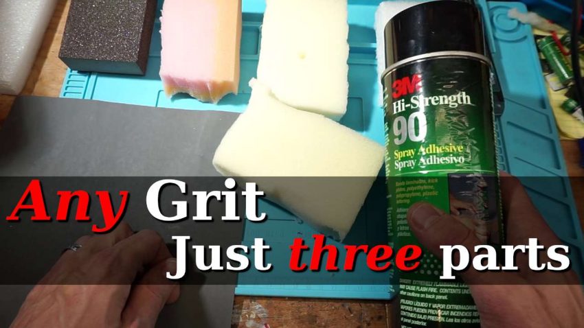
    So what to do? Make your own! While I don’t have 1200 grit sanding pads readily available, I do have 3M adhesive spray, foam, and a full index box of sandpaper.

    Choosing DIY Sanding Pad Components

    In addition to saving space by re-using already present components DIY sanding pads are a great way to use up odd cuts of sandpaper. Or sandpaper for a device you’re no longer using. Anything that is (or can be cut down to) roughly a hand-fitting shape will do.

    3M makes a range of spray-on high tack adhesives suitable for our task. I’ve chosen the 90 Hi-Strength spray. If 3M products aren’t available anything that could be used for automotive upholstery should do.

    And for the pads themselves I’ve re-used various shipping packaging and some unused bed foam. The trick to choosing the right foam is to find one that’s just pliable enough for the task at hand.

    Creating the Sanding Pads

    Laying up the paper and foam was straight forward. I laid out the pads and sandpaper face down, sprayed both sides liberally, then attached and flattened the sandpaper against the foam. With everything pre-cut it went together cleanly.

    On a side note, be careful what you’re spraying the foam on. My cutting mat came out a bit worse for the wear and lost some of it’s surface when the foam came off.

    And that’s it. There really isn’t too much work involved.

    How did the turn out? At the end of the video I went over which foam I liked the best. The denser white packaging foam seemed to be the best compromise between flexibility and durability for the bike tubes.

  • Glowing with LED LightBulb Filament

    Glowing with LED LightBulb Filament

    LEDs are the lighting of choice for economy and conservation. But they don’t have to look like sets of glowing dots. I have some attractive LED filament elements on my workbench to share with you today.

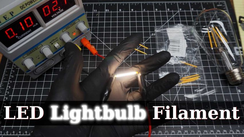
    These faux lightbulb filaments are yellow silicone or rubber diffusers over the tiniest bar light you’ve ever seen. When I put the LEDs under the microscope they were around an 0402/0201 (imperial) or 1005/0603 metric. I say about because measuring at that scale gets hard, fast.

    The light they give off was a bit surprising. While they’re in a yellow/orange sleeve the filament themselves are a neutral light. And the vendor on AliExpress lists them as “warm” but I’m guessing the light output is around 4000K~5000K range.

    Initially I had pushed the filament to 3.0v. As it turned out these are around 2.7v parts and running at 3v resulted in 300mA draw. Which was unfortunate as it took me a few minutes to notice it was running that high, since 3v at 100mA is 300mW. And that made it easy to accidentally do the wrong mental arithmatic.

    What else… these are strips of about 20 LEDs in series. Which makes sense given the 110v bulb styles which run two strips of parallel LEDs in series. That would give you 54v over each strip totalling out at 108, an almost perfect fit, with only a small amount of power to drop with a resistor.

    And you’ll want to be careful handling them. In this sample package of 10 half were broken straight out of the bag.

    In the future I’ll probably crack apart one of the LED filament lightbulbs shown in the video to give you a closer look at the inside. Because I’m curious what additional electronics they’ve got in there and if they’re using in-line resistors or something more complex.

  • SMD Spool Up for a Clean Workbench – DIY Solution

    SMD Spool Up for a Clean Workbench – DIY Solution

    Spooling up loose SMD part tape for surface mount components makes sense. So you’re suffering under the weight of plastic bags filled with tiny parts on paper rolls? Read on for a slick SMD Spool solution for storing them.

    Suddenly realizing my workbench was too cluttered (in the Phrozen Sonic Mini review) I decided to take action. But the eternal question, “where to begin?”, remained. So I started with the SMD tape lying around in bags.

    Various projects that I start on require surface mount components. The 1000 count tapes of resistors, capacitors, inductors, and ICs tend to collect up. I might need these in the future but they’re surplus to current requirements on the bench.

    So I’ve created a couple different sizes of SMD reel to store the surface mount component tape on. Each reel type has a locating stub and single screw hole for a flush mount M3 screw (of any sort, really) to hold it together.

    Also, the reel holders pictured in the background work very well for holding the narrow version of these spools. Printing them with PLA made them easier to remove from the printbed. PETG tended to shatter, and PLA allowed the narrow format to work on my Prusa i3 Mk3 3D printer.

    SMD Spool for a Cleaner Workbench

    And so my workbench is now somewhat cleaner. Without the spools lying around on or next to it one of the major annoyances has been tidied up.

    For the layout of the shop it also beats holding them on a long metal rod as I had been. Now I won’t have to remove every spool to get at the one (inevitably) farthest on the rack from the end.

    If you’re looking for a way to organize those SMD components these spools and manual rolling dispensers might be just the ticket.

    Links & Resources